|
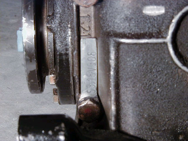
If you would like to know what kind of diff is installed
in your car, refer to the data tag located on the rear driver's
side of the diff. "S3.15" means a LSD 3.15 diff while a "2.93"
means an open end 2.93 diff.
Click on the picture for larger version.
|
|
|
|
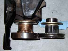
The diff swap is strait forward except for the
diff front shaft flange. This is the part of the diff that bolts
to the drive shaft. If the 3.15 diff came from a 750iL then
the front flange must be changed. The most important part of
the flange swap is resetting the preload (torque of the nut
that holds the flange to the diff). Almost all owners recommend
having the dealer or a mechanic with the right tools set the
preload. If it is not set correctly, the diff will fail in about
a year. In the figure the 540i flange is on the left while the
750iL flange is on the right. |
| |
|
| Removal Procedure |
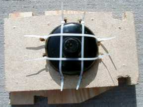
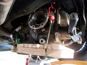
| Since the rear diff weighs about 95 lbs, the first
step was to come up with a way to swap out the diff if a second
person wasn't available. The design of what became known as
the "Differential Extraction and Insertion Device," or "Diff
Lift" for short, can be seen in figure 3. The outline of the
diff was traced on to one piece of ½" plywood. The plywood piece
were screwed to two ½" pieces of particle board and notches
were cut into the sides of the plywood to secure the bungee
cords. The bungee cords work well in this application since
some tweaking while extracting and inserting the diff is required.
Secure the Diff Lift to the cup of a floor jack with 8 tie wraps.
The floor jack is then used to lift and lower the diff, see
picture. |
|
|
|
|
|
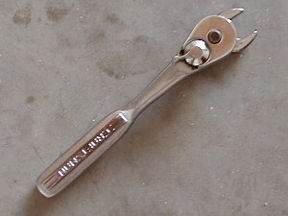
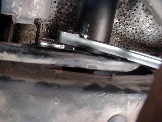
Start by removing the 6 drive shaft nuts. Since a socket
wrench will not fit into the area needed, use a 16mm open
end wrench or open end socket attachment. Since these are
lock nuts they must be replaced with new ones (the dealer
or any part store has them). Put the car in gear to lock the
drive shaft in place while loosening the bolts. Take the car
out of gear to rotate the drive shaft to the next nut. Note
that the drive shaft bolts cannot be removed. The Bentley
book recommends hanging the drive shaft from the car body
using wire. On the 95 540i6, the exhaust system runs right
under drive shaft and offers adequate support.
|
|
|
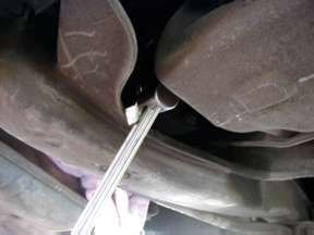
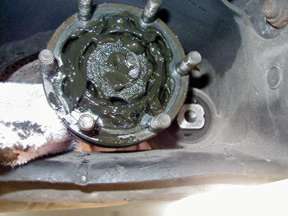
Using an 8mm allen wrench (preferably an allen
socket attached to a pneumatic socket wrench), unbolt the half
shafts (6 bolts each), see figure 7 . Use the parking brake
to hold the shafts in place while loosening the bolts. It is
recommended that both sides be done at the same time to reduce
the amount times needed to operate the parking brake. More than
likely these are the locking style nuts and must be replaced.
Support the half shafts with wire or allow them to lie across
the suspension. |
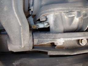
| Disconnect the speedometer wire (located on the
rear of the diff, passenger's side). Position the Diff Lift
under the diff, barely touching the diff (you want to support
the diff while unbolting it but you don't want to bind the bolts). |
|
|
|
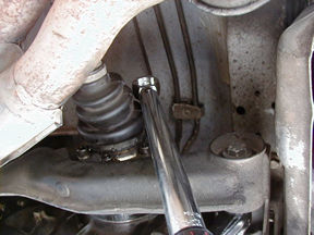
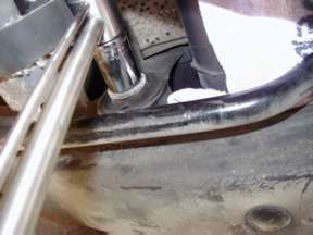
Secure the bungee cords around the diff. Unbolt
the single front mounting bolt (located on the passenger's side
of the drive shaft) using a 19mm socket, open end wrench, or
open end socket attachment, see picture. Before you unbolt the
two rear mounting bolts make sure the diff lift with bungee
cords is in place or an extra set of hands are in place. Also
note that the rear of the diff must come DOWN first to clear
the mounting bracket and then slide back to allow the input
flange to slide off of the drive shaft bolts. |
| The drive shaft flange will articulate to compensate
for the angle in which the diff comes out. Next, unbolt the
two rear mounting bolts using a 19mm socket. Remove the diff.
|
|
| Next, if the front input flange from the 3.15
must be swapped out, use a marker and index the bolt position
with the nut. This is a good reference when you put the correct
flange on and set the preload. The marks should line up pretty
close if not right on. |
|
|
The book recommends replacing the rear end fluid
after the diff is reinstalled. This is not exactly the easiest
way to do it. Several mechanics recommended changing the oil
before reinstalling the diff by leveling the diff on the ground
with shims and then adding the oil. Don't forget many rear end
oils require an anti-rattle additive. The 88 750iL 3.15 LSD
requires 2 qts of hypoid SAE 90/GL-5 LSD rear gear oil. The
drive shaft and diff flanges are packed with grease. Repack
the diff flange with grease. |
| |
|
| Installation Procedure |
|
Please note that the tightening torques recommended below
come from the Bentley Book. When the diff is reinstalled be
sure to line up the diff front flange holes with the drive
shaft bolts. Insert the front of the diff first and make sure
all of the drive shaft bolts go through a hole in the diff
flange. Next, rotate the rear of the diff up and into position.
This requires some careful tweaking. See figure 10. Insert
the rear mounting bolts and the front mounting bolt. The recommended
torque for the rear bolts is 77nm/57 ft.lbs. The recommended
torque for the front bolt is 123nm/91ft.lbs. Note that a standard
torque wrench will not fit into area needed to tighten the
front mounting bolt. A recommend procedure for torqueing down
the front bolt is to use a open end socket attachment on your
torque wrench. This will increase the wrench approximately
1 inch. Reduce the required by approximately 1-2 ft.lbs. to
compensate for this. See picture.
Next, install the drive shaft lock nuts. The recommended
torque is 64-70nm/47-52 ft.lbs. (see the Bentley book). Once
again a standard torque wrench will not fit into area to tighten
these nuts. Use the procedure recommended for the front mounting
bolt to tighten the nuts. Use a cross tightening pattern (like
what is used for wheel lug nuts). Once again, put the car
in gear to lock the drive shaft in place while tightening
the bolts. Take the car out of gear to rotate the drive shaft
to the next nut. Mark the nuts with a marker as a reminder
as to which nuts have been tightened. Reconnect the speedometer
plug. Reinstall the half shaft bolts using 83nm/61 ft.lbs.
Use the cross tightening pattern. Once again, use the parking
brake to hold the shafts in place while torquing down the
bolts. It is recommended that both sides be done at the same
time to reduce the amount times needed to operate the parking
brake.
Recheck everything, lower the car and enjoy.
Thanks
to Jason Blitz 
|