|
I wired in the pre-wired plug (that connects to the unit)
first, before plugging it in.
On the unit itself:
· RED - Constant 12v
I first crimped a forked terminal onto the RED wire. On
my car, under the back seat (pulls up) on the RIGHT there
was a black plastic housing (looks identical to the fuseable
link box in the engine bay) with a big red wire going in and
bolted to a big black wire going out. I carefully opened the
plastic cover and loosened the nut - with a socket, making
sure you don't touch any metal other than the nut! Then slide
the crimped terminal under the nut and do the nut up again.
I was careful not to break the connection made by the red
wire incase it affected any of the cars systems.
· BLACK - to NEGATIVE / GROUND
Again, crimped a fork terminal on the wire first. On the
metal 'wall' next to where the RED wire has just been connected,
there should be a nut (probably with paint on). If you undo
this you'll be able to slide the forked terminal in and do
the nut up again. I measured this to check if it was a good
ground, and it was fine, as the nut and the face it tightens
onto are bare metal - no paint!
· YELLOW - to switched 12v (comes on when ignition
is on)
This was a bit trickier to find. On the LEFT of the space
under the back seat is the central locking control unit and
some orange relays. Using a small screwdriver you can release
the little tab holding the 3 relays in place and lift them
up a bit to inspect the wires going into them. I think that
it was the middle of the 3 relays, but not sure, that has
Purple/Black wire (looks a bit fatter than the others) going
into it, which showed on the meter as going on and off with
the ignition, so I opted for this one. By the LEFT corner
you'll see a load of wires... find the Purple/Black fat one!
Once I'd found it, I used a Scotch-lock (SL) (one of those
plastic clips with a metal insert that you clamp over the
two wires you want to connect) and just clamped it onto the
wire so I could measure it again to check. Proved OK, so undid
the SL and put the YELLOW wire in and clamped shut to connect
them both.
I didn't use the GREY or ORANGE wires, so cut any exposed
wire off them and then taped the ends with insulation tape.
|
| Right then, this was a pain…coupled with
the fact that the instruction booklet is not set out particularly
well, having the worded description for the positive pulse wiring
underneath the diagram for the negative pulse wiring….well,
I blew one of the fuses by reading the words & following
the diagram!
Here's the correct diagram (the 2 SPD relays
are the 2 relays attached to the DLS!)

Click to see larger version
1. Open the boot (or 'trunk' if you prefer!) and undo the
4 plastic screws (each move a ¼ of a turn) on the trim
on the boot lid itself. Unhook it over the rubber bump stops
and pull it dow so you can see the lock mechanism and wires
and bits. Make a note of where the solenoid is before you
undo it, as the position is important for it to work properly.
The solenoid is held in place by 2 brass looking bolts (about
6 or 8 mm) - you should be able to see the near the black
latch on the inside of the boot lid. By the key lock barrel
(on the inside) you will see a bar with a 900 bend the end
that sits in a plastic bush - this bar is attached to the
solenoid and you need to push the bar out of the bush before
the solenoid will come out. Undo the two nuts and remove the
solenoid, leaving the wires plugged into it! It's a bit of
a fiddle, and is easier if you take the connecting bar out
of the solenoid end as well.
2. With the solenoid out, you can open the top of the connecting
plug to reveal the wires, which convieniently have round holes
in to poke the meter into! By locking and unlocking (pull
and push on the solenoid you've just got out) you can measure
the voltages on the 5 pins exposed. Here's what I found:
RED/BLACK +12v all the time
WHITE +12v pulse when locked, then 0v at rest in locked position.
WHITE/GREEN +12v when unlocked / 0v when locked / 12v when
actuator at rest unlocked
BLUE +12v Pulse when unlocked / 0v when at rest in unlocked
position
WHITE/BLUE +12v when locked / 0v when unlocked / +12v when
actuator at rest locked
When DEADLOCKED with the key:
· All 0v except WHITE/BLUE and RED/BLACK, which showed
+12v
The two additional relays (not the DLS) that I mentioned I
didn't use, are for if you want to protect the solenoids from
damage that can occur if the door are deadlocked with the
key, then tried to unlock by the remote. I didn't do this,
as the deadlocking had ben playing up and I didn't want to
use it anymore. If you don't install these relays just remember
when you've deadlocked the car! www.mypushcart.com can e-mail
you the diagrams if you want to fit them.
All the wires go back to the load of wires by the central
locking control unit, and it will help matters if you can
get some of the tape off to make it easier to separate the
wires.
This is how I wired it up (again, using Scotch-locks), and
everything is working fine:
DLS Wire Central Locking Wire
GREEN WHITE / BLUE
BLUE WHITE / GREEN
PURPLE RED / BLACK
|
DLS Wire
|
Central Locking Wire
|
|
Green
|
White/Blue
|
|
Blue
|
White/Green
|
|
Purple
|
Red/Black
|
I did the testing the wires with the SL crimped on first,
before connecting the wires…..just to be certain!
Once everything was plugged in, I programmed the unit as
per the instructions supplied.
Finishing Off:
The DLS relays I mounted on one of the screws on the central
locking control plastic cover. One screw is easily accessible
and is nearest the back of the seat…you can't miss it.
I took this scerw out, put the DLS relays in between the 2
halves of the plastic cover and lined up the hole in the relay
with the screw hole, then put the screw back in to clamp it
in place. The relays are really light, so I figured this should
be ok.
The main unit itself has two mouting tabs with holes in.
Just above where I connected the black GROUND wire, there
is a threaded bolt hole - I found a bolt with the same thread
and fastened the unit to the metal 'wall' securely. Again,
it is not heavy at all and was held very firmly in place.
The aerial wire. I pulled off the rubber/felt trim around
the door frame and then fed the wire into it and pushed it
back in place, so the wire ended up sealed in around the door
frame - which gave quite good reception and was nicely out
of the way.
Things to Note:
The system CAN operate the full closure system should your
E34 have it (normally operated by holding the key in the lock
or deadlock position). When the system is wired as described
above, the full closure will not work. The reason for this
( I think) is that the boot (trunk) lock doesn't operate the
full closure when using the key - hence as the system is wired
up off this set of wires, the full closure won't work. If
you can be bothered to try and figure out the lock/unlock
wires from in the drivers or passenger doors, I guess it should
work. I just decided that it would be considerably easier
to use the boot lock wires, and also I quite like to leave
he sunroof or windows slightly open in the summer when locking
the car up.
REALLY IMPORTANT>>>>>(my disclaimer!)
What I have described I in these pages is EXACTLY what I
discovered, tried and did, and I hope that it will help others.
As we all know, new BMW bits are not cheap, and I was very
worried about damaging solenoids or the central locking control
unit.
AS MUCH AS I HOPE THIS HELPS, IF YOU ARE UNSURE, CHECK
WITH AN AUTO-ELECTRICIAN OR YOUR LOCAL ALARM DELAER AS I WOULDN'T
WANT ANYONE BREAKING THINGS…..THIS IS AFTER ALL ONLY
MY TAKE ON THINGS AND I DON'T DO THIS FOR A LIVING!
|
All,
I installed my keyless entry system last night. I thought I'd
pass on what I learned in the process. It's cheap, easy, and
quick if you know what you're doing. First, all E34's have positive
trigger or output for the door locks! Many other cars have negative
trigger. So, you need a keyless system that can do positive
trigger or you need to buy a few extra parts to turn the negative
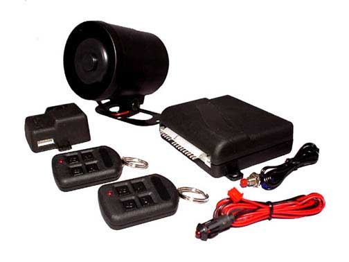
trigger system into a positive trigger. I bought my keyless
entry system from www.mypushcart.com. It was the Crimestopper
845RKE. It cost $40 including priority mail delivery. But, it
doesn't have positive trigger. So, I had to also buy two 30
amp relays and the prewired sockets for them. I bought the relays
and sockets from a local car stereo and alarm place for $7.50
total. You can also go to a place like www.audio-etcetera.com
and buy two 30 amp relays (CRI-CS-402A, $1.66 each) and two
prewired sockets (CRI-CS-SRS, $0.96 each). It's easy to wire
in the relays - the manual that comes from Crimestopper shows
you how. If you can follow a map, then you can wire this in.
Crimestopper also makes a model 855RKE that has the positive
trigger built in (other manufacturers also have them). I could
have bought that and saved myself a little grief but I didn't
know I needed positive trigger.
Basically, when installing the system, you
need to find a ground, a constant +12 volts, the lock wire
and the unlock wire. If you want your locks to lock when you
start your car and unlock when you shut it off, then you also
need to find a +12 volts that comes on when the engine is
running. I didn't wire mine up to chirp the horn or flash
the lights so I can't help you there. It also pays to buy
some low voltage tap-ins. I got a package of them from Radio
Shack (#64-3053) for $1.69. They allow you to crimp your keyless
entry wire onto the existing wire rather than cutting into
the wire and soldering. You just squeeze them on with a plier.
I've had good luck with them.
Disclaimer: What follows is my take on things.
I am not an engineer. Don’t hold me responsible if you
blow a fuse or something. I’ve been as careful as possible,
but verify what I’ve written by looking at your own Bentley
manual or by talking to a pro or another person who’s
done this. End of disclaimer. For '92, ’93, and '95 E34's,
the system installs under the back seat on the passenger side.
Look for the 12-pin plug near the battery where the alarm
module would plug in. The lock wire is white/red/yellow dots.
The unlock is blue/red/yellow dots. The brown/orange wire
is the ground, the red/gray wire is the constant +12 volts,
and the violet/white wire is the one that is +12 volts when
the car is running. 1994 E34’s are the same as above
except the constant +12 volts is yellow wire on the alarm
plug and the ground is brown. Sorry, but my Bentley’s
doesn’t show which wire is the +12 volts when the car
is running.
For '89 through '91 E34's, the system installs
in the kick panel near the driver's left foot. The lock wire
is white/red/yellow dots. The unlock is blue/brown/yellow
dots. You should be able to find a red wire for the constant
+12 volts (here’s when a cheap multimeter is handy) and
a small screw or something for the ground. I don’t know
where to find the +12 volts that is hot only when the engine
is running.
The systems usually come with an LED that
blinks to help you program the system and it blinks when the
car is locked. I figured it may serve as a theft deterrent
so I installed it in the plastic panel that is behind the
right calf of a passenger sitting in the back seat on the
opposite side of the car from the driver. I led the programming
push button up behind the seat so it is behind the center
armrest in the back seat, behind the cover that's held up
with Velcro, and even behind a small flap in the rubber sound-deadening
material (my car doesn't have the ski boot). I didn't want
to have to pull up the back seat to re-program the remotes
or the system.
I hope this helps. I'm not affiliated with
Crimestopper or mypushcart.com or audio-etcetera.com. They
were just the places I found on the web. There are a lot of
good systems out there. Any of them should work as long as
they do positive trigger (or you buy the relays and sockets
and spend an extra 20 minutes wiring them in).
Chris I.
Clearwater, FL
'95 525iA with keyless entry!
Double-locking (at least in my '92 525i) is triggered by
sending 12V to both the lock and unlock wires at the same
time. All you need to do to enable double-locking is to solder
a diode between those two wires. A cheap 1n5401 (available
at Radio Shack) will do the job just fine. Solder the end
of the diode with the solid line on it to the unlock wire,
and the other end to the lock wire. The diode lets the voltage
go to both wires when locking, and only the unlock wire when
unlocking. It works by letting current flow through the diode
from the lock wire to the unlock side during the lock process.
Then it blocks the current to the lock wire when the unlock
wire receives power. If it works backwards, then change the
orientation of the diode.
I have an alarm system that I bought from my local electronics
wholesaler for about $60. It has most of the features of the
big name alarms like code jumping, lock when the ignition
is turned/unlock with key off, flashing lights, dual-level
aux input, etc. The cool thing is that when the doors lock
when I start my car, they don't double-lock -- there must
be some logic in BMW brain somewhere that prevents the car
from double-locking with the key is in the ignition.
I hope this helps!
Lito Reyes
'92 525iM Sharked!
Here's what I came up with. This should apply to '92/'93/'95
E34's. Like Chris said, if you explode your car or something,
it's your own damn fault :)
Please note that it's entirely possible that my cause and
effect is faulty. This is just what I traced down using a
trusty test light. BTW, a test light like mine is handy for
this kind of work. It's one of the ones that looks like a
screw driver with an alligator-clip wire emanating from the
top. The real secret is that it eliminates those pesky short
circuits because it just lights up if you are connecting opposite
polarities. If you alternately hook the alligator clip to
positive or negative, then you can probe for triggers because
the bulb's filament completes the circuit, and the trigger
circuits don't even pull enough current to light it up. This
obviously isn't a good idea where sensitive/high-impedance
drivers are involved, i.e., fuel injector circuits in some
cars or airbag wiring; in those cases, dig out the DMM.
|
Wire Color*
|
Function |
|
brown/red
|
timed dome lights (~7 sec) (-pulse)** |
|
red/white
|
? shows neg always |
|
blue/red
|
unlock (+pulse) |
|
white/red
|
lock (+pulse) |
|
blue/green
|
blink parking lights (- pulse) |
|
black/blue
|
? shows no signal |
|
brown/violet
|
goes (-) when either rear door opened |
|
brown/blue
|
goes (-) when either front door opened |
|
brown/white
|
timed dome lights (~15 sec) (-pulse)** |
|
brown/orange
|
ground |
|
violet/white
|
+ when car running |
|
red/gray
|
+ constantly |
|
|
|
*most wires also have little yellow dots
on them
**dome rocker switches in the forward position |
In my case, I have a DEI keyless entry that came with all
kinds of goodies I probably won't use. I will mention some
of the features I did use, and how. The great thing is that
you don't have to go anywhere except the plug under the rear
seat. I'm pretty anal retentive and solder in everything instead
of using taps; even so, the actual installation only took
about 30 minutes.
1. Unlike some systems, this one supplies both positive and
negative signals for lock/unlock. Unfortunately, this isn't
done with four separate wires, but with two. How? Each wire
does double-duty, carrying the inverse of what the other does;
for example, one wire is + lock, - unlock. The other is the
opposite. This causes a bit of a problem when trying to do
the double-lock action, since a single diode would still cause
a short circuit between the + of the lock circuit and the
- of the unlock (remember the other is always inverted). While
DEI might have put in circuitry to eliminate this problem,
I wasn't taking chances, so I used two diodes to eliminate
the possibility of + current going "back up" the
unlock wire (see lower circuit in diagram). This might not
be a bad idea even if your unit doesn't reverse polarities,
as the driver might still be sensitive to the onrush of current.
Thus far, we have lock and double-lock (whoo-hooo).
2. ...But we don't have window/sunroof rollup. That's because
my keyless unit only supplies a pulse for lock, not a constant
signal. This can be overcome (apparently) with add-on units
that DEI supplies, but I don't have no stinking time to wait
around ;) To add insult to injury, you can't program this
system to perform more than one channel function for the same
key (separate channels are controlled by either separate buttons
or unique combinations of two buttons pressed simultaneously).
I reasoned that it wouldn't be a *bad* use of the auxiliary
button to perform the rollup feature. The auxiliary channel
supplies a (-) signal as long as the button is pressed. As
a side note, I also couldn't just reprogram the auxiliary
channel to the lock button, because the unit needs a "proper"
lock signal to perform all the housekeeping it does (start
blinking the LED, flash lights, honk horn, whatever). First
the (-) signal was converted to (+) using a relay. Then a
couple more diodes were utilized to merge the unlock and aux
signals without screwing something up (upper diagram). BTW,
I happened to have about 20 of these diodes around, I bought
a pack of 25 a while back for another project :) So now, you
lock with the lock button, then press the aux button to roll
up the windows, etc. I'm not sure what the current draw would
do to an alarm system, though. It might think things are locked
up and something is malevolently using electricity.
3. All the other DEI channels are (-) trigger, so I plugged
them straight in to the dome light and parking light wires.
I could have triggered the domes on unlock from the lock wire
(remember that inversion thing?), but decided to use the "progressive
unlock" channel. This is normally used to unlock the
driver's door on the first press of the unlock, and the rest
of the doors on the second press. Now I can control whether
the domes come on before the door is opened, by pressing the
unlock a second time.
4. It's not horny :) Even though I'm sure the factory system
has horn blip confirmation, I couldn't find a wire from the
rear of the car to perform this function. Even if it did,
the horn relay only gets its constant + when the key is on
(the horn button supplies the -). Actually, supplying the
horn relay wire with a + positive signal when the car is off
will honk the horn. I don't know if this is by design or if
the other side of the relay is grounding through the windings
or filaments of other items in the same power circuit. Don't
laugh, the a/c relay on my Triumph is wired that way on purpose.
Since I was putting the lower dash back together, I tapped
into the relay wire and stowed a bundle under the carpet panel
next to the console, for future use without taking everything
apart.
5. I took advantage of the opportunity to wire in a few other
indulgences. These are items that it would be foolish to post
on the World Wide Web! Let's just say that I made thieve's
lives a little harder.
If anyone wants to/can elucidate or expand what I have here,
please let me know. Just shoot me an email at gear_head@excite.com.
|