- Phillips screwdriver.
- hex key to remove radio
- Needlenose pliers
- Diagonal cutting pliers
- Soldering iron
- Good tin/rosin solder
- Supply of 14 AWG stranded wire. I'd recommend red, black
and green insulation
- "vampire" wire connectors for connecting a wire
to an existing wire without cutting the existing wire
- Radio Schlock 275-218 DPDT relay (an SPDT will work also)
- An ohmmeter (DVM, preferably)
Before you start work, REMOVE THE NEGATIVE BATTERY TERMINAL
FROM YOUR BATTERY and ensure that your ignition is in the
off position (remove the key). If you don't, you may only
blow a fuse. But you could possibly blow your OBC. Or something
else. Given Murphy's ubiquity and caprice, you'll likely nail
something (or things that are) very expensive.
1. Remove the glove box and set it aside (see Bentley's,
513-4)
2. Remove the glove box cover (three Phillips screws: as you
look towards firewall, right, left near glovebox latch, left
near rear), disconnect the light and the switch. Don't break
the plastic tabs at the rear. Slide it towards you. Set it
aside.
3. Remove the ventilation duct and cover (see Bentley's 640-12,
figure 25). Set the assembly aside.
4. Remove the radio.
5. Remove the OBC by pulling the lever at the left rear of
the OBC towards you. The OBC will pull out from its connector
(26 pin IDC)
At this point, you have access to the OBC connector and its
associated wiring. The wires of interest on the OBC connector
are connected to pins 21 (black/white or black/white/yellow,
my car was the latter) and 9 (red/yellow, direct from fuse
f20). The Bentley calls out OBC pin 14 instead of 21. Do not
believe the Bentley. It is wrong. Pin 20 is likely not connected,
but if it were, it serves as a timer trigger for heating.
But I digress.
My car was built in 7/90. It doesn't have a sword, it has
a resistor pack. It also has the newer HVAC control. I only
paid attention to wiring diagrams EWD-125 to EWD-127. A cursory
glance at the '93 wiring tells me that this procedure MAY
work with the 1993.
Now for the relay installation:
6. The OBC connector at the rear of the panel slides to
the rightfor removal.
7. Cut the cable tie holding the OBC wire bundle to the green
cover for the IDC connector. Take care to not cut any wires.
8. "vampire" a 15" or so wire (I used white)
onto the pin 21 wire. Call this wire w7.
9. "vampire" a 15" or so wire (I used red)
onto the pin 9 wire. Call this wire w8.
10. Find a power wire that's always on that has sufficient
amp capacity (at least 15 amps). There are a number of candidates
relatively nearby. Carefully connect this wire (call it w3)
to the hot wire and run it to where w7 and w8 are.
11. You will see a 3 pin molex connector bundled with two
4 pin molex connectors mated with only one green wire connected
to each. Disconnect the four conductor connectors.
12. One of these green wires goes to the blower switch, position
2. The other goes to the resistor pack. Ring 'em out. The
latter should always have resistance on it relative to ground.
Call this wire w5. The former will show open if the switch
is in position 0. Call this wire w1. I used green wires for
w1 and w5.
13. You should now have five wires, labeled (you did that,
didn't you?) w1, w3, w5, w7 and w8. Grab the relay and figure
what pins
are which. The wire numbers that have been assigned correspond
to the connector numbers on the relay. If you wish, sleeve
them with
heatshrink tubing of an appropriate diameter before connecting
them to the relay. Solder them all into place. Ensure you
haven't
inadvertently bridged any connectors. Flow the solder! You
don't want any cold solder joints here. Trim excess strands
of wire away
from each solder joint. Slide the heatshrink down flush to
the relay and shrink it, if you used heatshrink.
You now should have the parked car ventilation feature
in place, once things are reconnected.
14. Reassemble the OBC IDC connector and its cover with
a new cable tie. The "junction" part of the cable
tie should be on the same
side as the socket side of the connector.
15. Slide the OBC connector back into place. Ensure that it
"clicks" into place.
16. Ensure that the OBC removal lever is set fully towards
the outside of the dash. Slide the OBC into place. If you
feel anything but mild resistance, DO NOT FORCE THE OBC INTO
PLACE. Check out why its not going into place.
At this point, you can test the installation. Reconnect the
negative battery cable. Turn the ignition to position 1. Press
the OBC timer
button. You should see "VENT" on the OBC display.
If you press the "S/R" button at this point, the
two LEDs on the timer button should
flash and the fan should come on. If you press "S/R"
again, the fan should come off. The OBC display will change
to "VENT on" and "VENT
off" on the button presses. Turn the key to position
2. You should be able to operate the fan normally with the
fan switch. Turn the switch
to position 0 and then to position 1. Press the OBC timer
button twice. You should see something like "00.00amT1"
on the OBC display. Enter a time using the "powers of
ten" buttons. "S/R" should set the time and
the left timer LED should illuminate. Hitting timer
again will bring up the t2 display, which is programmed similarly.
"S/R", after a timer has been programmed, toggles
its state (eg. if it's enabled---LED lit---and "S/R"
is pressed, the timer is disabled). The timer turn-on time
is not affected by the disable. When you're done, disconnect
the negative terminal of the battery.
If the above doesn't work as stated, you've got a problem.
It is very likely a wiring mistake. Disconnect the negative
terminal of the battery, if you have not done so. Go through
the instructions again, checking your work. Check fuses, especially
f20 and the fuse for the wire you tapped for the other "always-on"
12v. Check that the relay contacts are not touching each other
or something else. Be meticulous.
Be patient. If you get frustrated, walk away from it and do
something else. Have someone else check your work. You'll
eventually find out
what's wrong.
So you've tested things and you're satisfied it works. Time
to button things up:
17. Replace the radio.
18. Replace the ventilation duct.
19. Replace the glove box top cover. Ensure that you reconnect
the switch and the light.
20. Replace the glovebox.
Enjoy.
Notes from Janis S:
I would like to add some comments about this article that
can make life
easier for another people trying to repeat the procedure described
above.
1. I used standard automotive 12V 30A relay, which has different
pin numbers. So in my case they were:
w1 - 87a
w3 - 87
w5 - 30
w7 - 85
w8 - 86
2. There is no need to remove radio and OBC, you can use the
original BMW park heating/ventilation relay box connector
to connect wires w7 and w8.
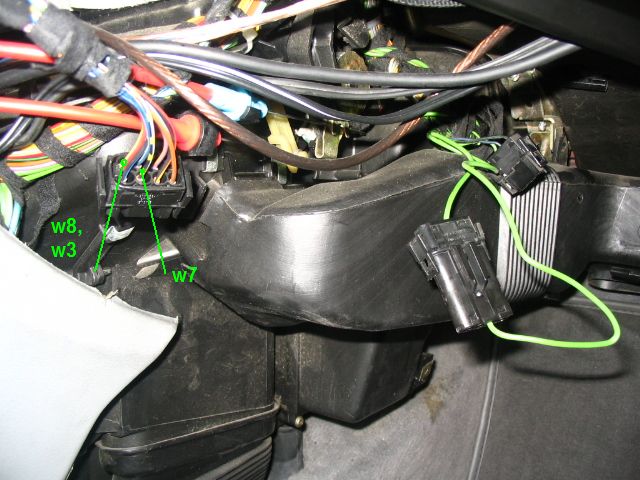
This is an unused 8-pin connector (shown in the picture) hidden
somewhere near to OBC. Connect red/yellow wire to w8 and black/white/yellow
wire to w7.
3. "Always on" power w3 can also be taken from the
same red/yellow wire, it is protected by 30A fuse that is
more than enough for blower, so wires w8 and w3 can be connected
together.
|